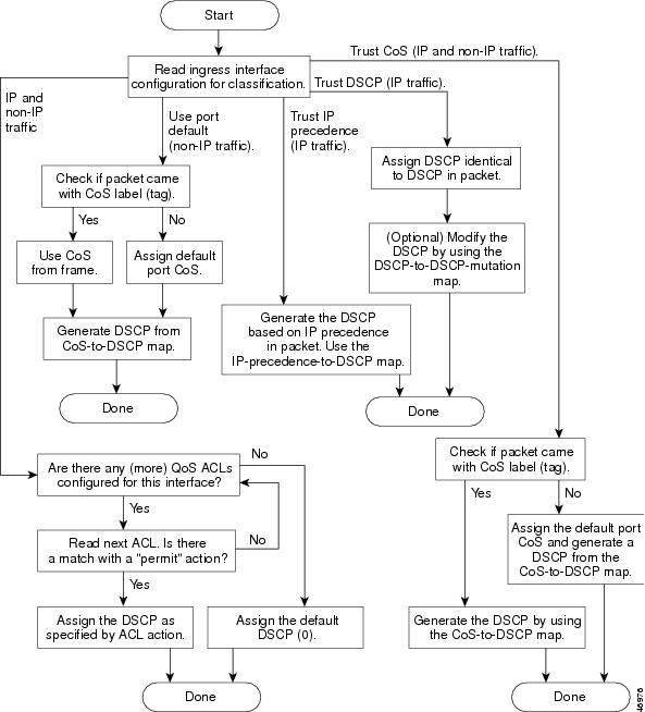
QoS – Classification and Marking
The first element to a QoS policy is to classify/identify the traffic that is to be treated differently. Following classification, certain “marking tools” can set an attribute of a frame or packet to a specific value. Such marking (or remarking) establishes a trust boundary that scheduling tools later depend on.
Classification and marking tools set this trust boundary by examining any of the following:
- Layer 2 parameters—802.1Q Class of Service (CoS) bits, Multiprotocol Label Switching Experimental Values (MPLS EXP)
- Layer 3 parameters—IP Precedence (IPP), Differentiated Services Code Points (DSCP), IP Explicit Congestion Notification (ECN), source/destination IP address
- Layer 4 parameters— L4 protocol (TCP/UDP), source/destination ports
- Layer 7 parameters— application signatures via Deep Packet Inspection, such as Cisco Network Based Application Recognition (NBAR)
You can only apply policies to traffic after it has been positively classified. To avoid the need for repetitive and detailed classification at every node, packets can be marked according to their service levels.
Similarly, marking tools can be used to indicate respective priority levels by setting attributes in the frame/packet headers so that detailed classification does not have to be recursively performed at each hop. Within an enterprise, marking is done at either Layer 2 or Layer 3, using the following fields:
802.1Q/p Class of Service (CoS)—Ethernet frames can be marked at Layer 2 with their relative importance by setting the 802.1p User Priority bits of the 802.1Q header. Only three bits are available for 802.1p marking. Therefore, only 8 classes of service (0-7) can be marked on Layer 2 Ethernet frames.
IP Type of Service (ToS) byte—Layer 2 media often changes as packets traverse from source to destination, so a more ubiquitous classification occurs at Layer 3. The second byte in an IPv4 packet is the ToS byte. The first three bits of the ToS byte are the IPP bits. These first three bits combined with the next three bits are known collectively as the DSCP bits.
The IP Precedence bits, like 802.1p CoS bits, allow for only the following 8 values of marking (0-7):
–IPP values 6 and 7 are generally reserved for network control traffic such as routing.
–IPP value 5 is recommended for voice.
–IPP value 4 is shared by videoconferencing and streaming video.
–IPP value 3 is for voice control.
–IPP values 1 and 2 can be used for data applications.
–IPP value 0 is the default marking value.
Many enterprises find IPP marking to be overly restrictive and limiting, favoring instead the 6-Bit/64-value DSCP marking model.
DSCPs and Per-Hop Behaviors (PHBs)—DSCP values can be expressed in numeric form or by special standards-based names called Per-Hop Behaviours.
There are four broad classes of DSCP PHB markings:
- Best Effort (BE or DSCP 0)
- RFC 2474 Class Selectors (CS1-CS7, which are identical/backwards-compatible to IPP values 1-7)
- RFC 2597 Assured Forwarding PHBs (AFxy)
- RFC 3268 Expedited Forwarding (EF).
There are four Assured Forwarding classes, each of which begins with the letters “AF” followed by two numbers:
- The first number corresponds to the DiffServ Class of the AF group and can range from 1 through 4.
- The second number refers to the level of Drop Preference within each AF class and can range from 1 (lowest Drop Preference) through 3 (highest Drop Preference).
DSCP values can be expressed in decimal form or with their PHB keywords. For example, DSCP EF is synonymous with DSCP 46, and DSCP AF31 is synonymous with DSCP 26.
NOTE:
IP Explicit Congestion Notification (IP ECN)—IP ECN (as defined in RFC 3168) makes use of the last two bits of the IP ToS byte, which are not used by the 6-bit DSCP markings.
These last two bits are used to indicate to TCP senders whether or not congestion was experienced during transit. In this way, TCP senders can adjust their TCP windows so that they do not send more traffic than the network can service. Prior to this method, dropping packets was the only way that congestion feedback could be signaled to TCP senders.
Using IP ECN, however, congestion notification can be signaled without dropping packets. The first IP ECN bit (7th in the ToS byte) is used to indicate whether the device supports IP ECN and the second bit (last bit in the IP ToS byte) is used to indicate whether congestion was experienced (0=”no congestion”; 1= “congestion was experienced”). IP ECN can be marked through a congestion avoidance mechanism such as weighted early random detection (WRED).


