QoS – Ingress and Egress Queuing using 2Q3T or 1P1Q3T
1P1Q3T – ingress queuing
As switch platforms have architectures based on oversubscription, they have been engineered to guarantee QoS by protecting critical traffic trying to access the backplane/stack-ring via ingress queuing.
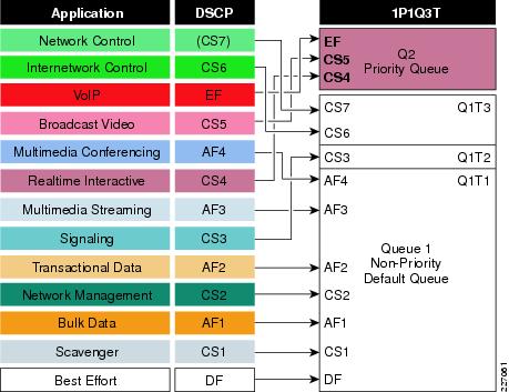
Ingress queuing can be configured as 2Q3T or 1P1Q3T, with the latter being the recommended configuration (as it supports the RFC 3246 EF PHB).
1P1Q3T ingress queuing is configured by explicitly enabling Q2 as a priority queue and assigning it a bandwidth allocation, such as 30%. Next, an SRR weight can be assigned to the non-priority queue, which in this case would be 70%. The buffer allocations can be tuned such that Q1 gets 90% of the buffers, while Q2 (the PQ) gets only 10%; since the PQ is serviced in realtime, it is generally more efficient to provision fewer buffers to it and more to the non-priority queues. After this, WTD thresholds can be defined on Q1 to provide inter-queue QoS; specifically, Q1T1 can be explicitly set at 80% queue depth and Q1T2 can be explicitly set at 90% queue depth (while Q3 remains implicitly set at 100% queue depth).
With the queues and thresholds set, then VoIP (EF), broadcast video (CS5), and realtime interactive (CS4) traffic can be mapped to the strict priority ingress queue. All other traffic classes can be mapped to the default (non-priority) ingress queue.
However, drop preference can be given to control plane traffic, such that network control (CS7) and internetwork control (CS6) traffic is mapped to the highest WTD threshold (Q1T3); additionally, signaling (CS3) traffic can be mapped to the middle WTD threshold (Q1T2). All other flows would be mapped to Q1T1.
1P3Q3T – Egress Queuing Model
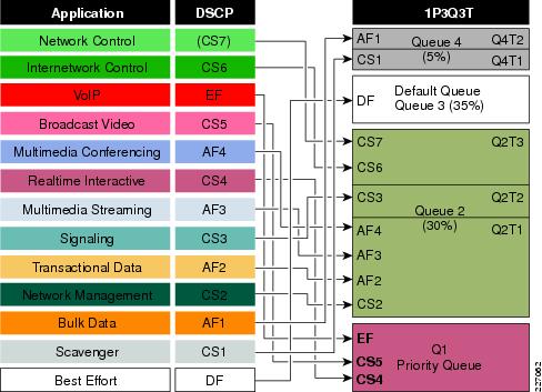
Egress queuing on some switches can be configured as 4Q3T or 1P3Q3T, with the latter being the recommended configuration (as it supports the RFC 3246 EF PHB).
(Two different egress queuing sets can be configured on the Catalyst 3750-E; however, to maintain consistent per-hop behaviours, it is generally recommended to use only one).
A unique feature of the Catalyst 3750-E is that it supports flexible buffer allocations to hardware queues, which may be dynamically loaned or borrowed against (as needed). Specifically, each queue can lend part of its buffering capacity, unless a specified minimum reserve threshold has been reached. Additionally, each queue may borrow up to four times its capacity from a common pool of buffers (which are not allocated to any specific queue) should these be available for use. The recommended buffer allocations for queues 1 through 4 are 20%, 30%, 35%, and 15%, respectively. Correspondingly, the recommended parameters for reserve thresholds and maximum (overload) thresholds for non-priority queues are 100% and 400%, respectively; for the priority queue, all thresholds should be set to 100%
Once the primary queuing set has been configured for 1P3Q3T egress queuing, WTD thresholds can be defined on Q2 and Q4 to provide intra-queue QoS. Specifically, Q2T1 can be explicitly set at 80% queue depth and Q2T2 can be explicitly set at 90% queue depth (while Q3 remains implicitly set at 100% queue depth). Also, Q4T1 can be explicitly set at 60% queue depth, while the other thresholds for Q4 remain at their default values (of 100% queue depth), with the exception of the maximum (overload) threshold, which can be set to 400%. This last setting allows for even Scavenger & Bulk traffic to benefit from the extended buffering capabilities of this platform, especially when considering that these are the least favored flows from a bandwidth perspective and thus will likely need the deepest queues.
With the queues and thresholds set, then VoIP (EF), broadcast video (CS5), and realtime interactive (CS4) traffic can be mapped to the strict priority egress queue (Q1). Network management (CS2), transactional data (AF2), multimedia streaming (AF3), and multimedia conferencing (AF4) traffic can be mapped to Q2T1. Signaling (CS3) traffic can be mapped to Q2T2. Network (CS7) and internetwork (CS6) traffic can be mapped to Q2T3. Default (DF) traffic can be mapped to Q3, the default queue. Scavenger (CS1) traffic can be mapped to Q4T1, while bulk data (AF1) is mapped to Q4T2. These 1P3Q3T egress queuing mappings for the Catalyst 3750-E are shown here:
vv


